This series of posts describes how I hacked a low cost (€37 from Maplin) Efergy Elite electricity monitor to obtain real time power use data and to record and chart this data with the aim of understanding how electricty is used in the home and how to reduce consumption.
Describing the entire solution in one go is going to result in an excessively long post, so I'm going to break this into several parts over the next few weeks. In this post I'll describe the process involved in getting access to the raw data from the sensor unit.
The term 'smart' in the title is a misnomer. All I want to do here is record real time (at least several samples per minute) power use into a computer system. A true 'smart' meter will do telemetering, facilitate demand based tariffs, feed-in tariffs etc.
The problem with low cost energy monitors is you only get the current instantaneous usage and perhaps hourly, daily and weekly averages.
What I want is something that looks like this:
In this chart I can see my coffee machine (left on accidentally), the oven (not much I can do about that) and the fridge. From that chart I can figure the base load due to broadband router, WiFi access point, DVR etc and work out the average use of my fridge (by estimating the duty cycle and subtracting the power level while on from the base load).
So, how did I arrive at this chart?
I had an Efergy Elite electricity monitor which I received as a gift a few years ago. The product comprises a current transformer sensor which clips on to the utility meter outside. This transmits a power reading every 6 seconds over a 433MHz radio to the receiver unit indoors. The receiver has a LCD which displays instantaneous power use, and hourly, daily weekly averages (and other less interesting stuff like CO2 emissions). Photos of the sensor, receiver and internal electronics are here. There is no computer interface to tap into this data, so one needed to be hacked in.
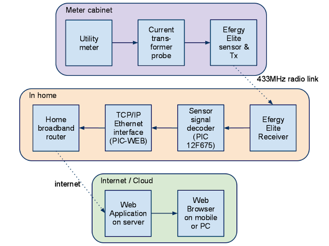
There is a block diagram of my solution:
Looking at the receiver unit electronics, there is a test pad located near the radio part of the PCB. (The A72C01AUF chip to the bottom left of the test pad does all the radio heavy lifting both in the sensor and receiver).
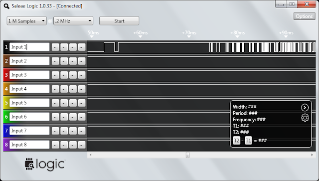
Looking at the signal at this point with an oscilloscope one can see there is burst of logic level (0/5V) signals every 6 seconds. This would seem to be the base band output from the radio. An oscilloscope isn't the most useful tool for decoding digital IO if there are more than a few bits involved. I put a recently purchased Saleae 'Logic' (logic analyzer) on the task and this is what the signal looked like:
This signal didn't seem to make much sense. So I also simultaneously recorded the sensor's digital input line to the transmitter (pin 18 on the sensor's MCU – which by the way is a GSSP 22682X01 – a difficult chip to locate a datasheet for).
Thanks to the logic analyzer's big picture it seems there is an initial block of what looks like random noise preceding the actual data (I'm guessing this is just noise from the radio transmitter powering up).
Now looking more closely at the actual data:
The data is encoded using a digital equivalent of Frequency Shift Keying (FSK). A logic 0 is represented by three long pulses of 2ms duration in total (a low frequency) and a logic 1 by 4 shorter pulses totaling 2ms also (a high frequency).
Decoding this could be achieved with analog circuitry but this would involve a handful of (relatively) expensive passive components. Instead I chose a pure digital technique. I used a simple pattern matching algorithm to look for 3 successive long pulses or 4 successive short pulses and ignore anything else (code appended below).
From bits to bytes
So now I have a string of logic '0's and '1's. The next problem is to determine where the byte boundaries are.
Fortunately each data packet starts with the following 4 bytes: 0xAB 0xAB 0xAB 0x2D. This helps with synchronization. When looking for the start of data I shove the bits into a shift register until I get a byte value of 0xAB. I take all subsequent bits as groups of 8 to form the bytes of data. After the first 0xAB I ignore all subsequent byte values of 0xAB until I get a 0x2D. I am now at the start of the packet payload.
A typical packets look like this:
AB, AB, AB, 2D, 00, 0B, 5A, 40, 98, 00, 02, 00, 41After some experimentation this is what I believe the packet consists of:
| 0 | Sync, always 0xAB |
| 1 | Sync, always 0xAB |
| 2 | Sync, always 0xAB |
| 3 | Sync end, always 0x2D |
| 4 | ? always 0x00 |
| 5 | Device address high byte (always 0x0D for my device) |
| 6 | Device address low byte (always 0x5A for my device) |
| 7 | sbssaaaa where s = bits of sampling period, b = battery low indicator (0 = low) and aaaa is the upper 4 bits of sensor A. 0-00---- = 6s sampling, 1-01---- = 12s sampling, 0-10---- = 18s sampling. It's odd that ‘b’ is sandwiched in among s bits. |
| 8 | Least significant 8 bits of sensor input A (nearest MCU edge of board) |
| 9 | ? probably upper 4 bits of sensor B and C. |
| 10 | Least significant 8 bits of sensor input B (middle) |
| 11 | Least significant 8 bits of sensor input C |
| 12 | Checksum (arithmetical sum of bytes 4 - 11). |
So in summary, each packet comprises a unique sensor address, the sampling rate, a battery low flag and 3 x 12 bit ADC values for each of the sensor's three inputs (normal domestic power is single phase, so only one input is used. A three phase system would use all three inputs) and finally a checksum of the contents of the packet for data integrity.
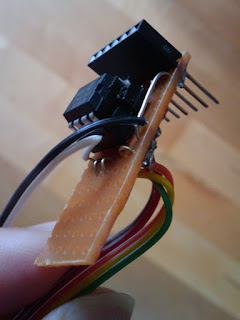
I soldered a small (12F675) PIC MCU to a piece of veroboard (pictured right) and wrote a program to decode the baseband signal from the radio and convert that to actual data.
The PIC code used to decode the radio baseband signal is listed below (this excerpt is not the full PIC application – contact me if you need the lot):
The next problem is to figure how to translate these ADC values to Amps (and by multiplying by 230V to Watts) and how to feed this data to a database for recording and visualization. These will be covered in subsequent posts.
Related Links
Updates to post:
- 4 Jan 2011: Added related links section.
- 16 Apr 2011: Part 2 published.
#include#include "efergy_config.h" #include "efergy_elite_decode.h" byte getPulseWidth(); byte getBit (); byte getByte (); void resync(); byte t3,t4,tm; /** * Decode baseband radio signal from Efergy Elite receiver. * * Packet consists of a radio preamble of what seems * like random noise for about 200ms followed by a quiet period * of 100ms followed by data for 200ms. Encoding is a FSK type * scheme. * Logic 0 is represented by 3 cycles of "low" frequency square * wave (period 8t per cycle). * Logic 1 is represented by 4 cycles of "high" frequncy square * wave (period 6t per cycle). * Logic 0 and Logic 1 have the same period of 24t which is * very approx 2ms [confirm]. Ie t ~= 83 microseconds. * * +---+ +---+ +---+ * | | | | | = Logic 0 * +--| +---+ +---+ * +--+ +--+ +--+ +--+ * | | | | | | | = Logic 1 * +-+ +--+ +--+ +--+ * * Decoding this not but looking at frequency, but looking * for 3 long pulses in succession or 4 short pulses. * * Data has 3 bytes of synchronization: 0xAB, 0xAB, 0x2D. * Look initially for 0xAB to get byte boundary synchronization. * Then look for 0x2D to flag start of actual data. * * All inter-pulse calculation must be complete * within 64x5 microseconds ie ~ 300 microseconds or 300 instructions @ 4MHz) */ byte decodeEfergy(unsigned char *buf) { byte i,bitc=0, bytec=0, b=0; byte t,pt; //byte bufIndex=0; unsigned int rt=0; t3=0x1a; // short pulse duration of 3t t4=0x23; // long pulse duration of 4t tm = 0x1e; // mean of short and long pulse, ie 3.5t resync: // Look for sync bit sequence // TODO: update: just look for AB followed by 2D. // Get byte boundary sync while (b != 0xAB) { b = (b<<1) | getBit(); } for (i = 0; i < 8; i++) { b = (b<<1) | getBit(); } if (b != 0xAB) { goto resync; } for (i = 0; i < 8; i++) { b = (b<<1) | getBit(); } if (b != 0x2D) { goto resync; } b=0; // 9 bytes left to retrieve do { b = (b<<1) | getBit(); bitc++; if (bitc == 8) { buf[bytec++] = b; b=bitc=0; } } while (bytec < 9); // Calculate checksum byte cs = 0; for (i = 0; i < 8; i++) { cs += buf[i]; } // Display checksum fail if they don't match if (cs != buf[8]) { return 4; } return 0; } byte getByte () { byte i,b; for (i = 0; i < 8; i++) { b = (b<<1) | getBit(); } return b; } byte getBit () { char t; byte nshort=0,nlong=0; while (1) { t = getPulseWidth(); if ( t < tm) { nshort++; } else { nlong++; } // Check for anomalous condition if ( (nshort>0) && (nlong>0) ) { nshort=nlong=0; if ( t < tm) { nshort=1; } else { nlong=1; } } if (nshort == 4) { return 1; } if (nlong == 3) { return 0; } } } byte getPulseWidth() { byte t=0; while (RADIOBB_PIN) { CLRWDT(); } while ( ! RADIOBB_PIN) { t++; } return t; } void resync () { byte pt,t; restart_resync: // Can have either 3t (short) or 4t (long) pulse. Get pulses of // two different lengths. 3t is the short pulse, 4t is the long one. pt = getPulseWidth(); do { t = getPulseWidth()+2; } while (t - pt < 4); t -= 2; if (pt < t) { t3 = pt; t4 = t; } else { t3 = t; t4 = pt; } if (t4 < 0x1A) { //TXREG='s'; goto restart_resync; } if (t4 > 0x30) { //TXREG='l'; goto restart_resync; } // Didn't have to do this at the sensor, but receiver has a lot more incoming crud if ( ((t4>>2)*3 ^ t3) & 0b11111100 ) { // (t4/4)*3 ~= t3 (ignoring 2 LSB of precision) //TXREG='?'; goto restart_resync; } // tm is mean of t3 and t4 tm = (t3+t4)>>1; byte b=0; // Look for sync bit sequence while (b != 0xAB) { b = (b<<1) | getBit(); } }

.png)


